tldr; Follow these simple steps to repair transfer switch for automatic switching from shore power to RV Solar.
Need to repair the automatic transfer switch for your RV solar power system? The best solution is to replace the transfer switch with the same model. And then, pay close attention to wiring all connections identically the same. With this post I’ll show you everything you’ll need and provide step by step instructions below. Complete with parts list, photos, manual downloads, and important warnings.
Why Repair Transfer Switch
For us, the answer to why we replaced our transfer switch was simple. It stopped working. However, this wasn’t the first time I took apart the relay box. That was when we had that dangerous RV electrical mishap. ???? We don’t say the F-word around here!
After my first transfer switch repair job, we never had any more close calls. Subsequently, the transfer switch simply stopped working one day. When disconnecting the shore power at one RV Park, I heard a loud click. It sounded more like a snap. When we arrived at our next location we had no shore power.
I never dreamed the transfer switch would have been the problem. Therefore, I did some serious troubleshooting. We had power at the pedestal, but not the other end of the cord. I thought the snap I heard was a contact in the plug breaking. So I first replaced the plug. (If you ever need to d that, I have post for that: How to Repair Dangerous RV Electric Cord) But I digress…
Thankfully for you, I found these handy manuals and troubleshooting guides:
PDI 5100 Series Troubleshooting Guide
PDI 5100 Series Installation Manual
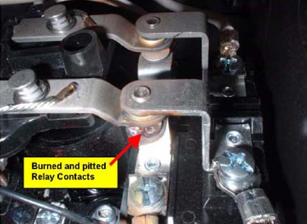
Another common reason for a bad transfer switch is burned and pitted contacts on the relay. If the relay contacts are pitted, the generator voltage is dropping under load. As a result, if this problem occurs you must repair or replace the generator and the complete automatic transfer switch.
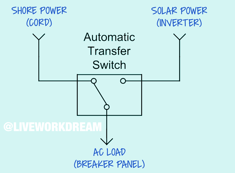
How an Automatic Transfer Switch Works
The ATS is a transfer relay that will automatically transfer the source of electricity from one source to another. The Progressive Dynamics Transfer Switch is a vital component of our RV solar power system.
Standard Transfer Switch Operation
- When shore power is applied, the relay is at rest and power is transferred to the panel.
- When generator power is applied there is a 20-45 second delay and then the relay activates transferring generator power to the panel.
- If shore power returns while the generator power is present nothing will happen.
- When the generator power removed the relay will drop out and allow the shore side to supply power.
Since we enjoy boondocking so much, we have the switch wired to instantly provide power from the inverter. This is basically the opposite of standard switch operation. If you can wait 20-45 seconds for power, the relay will work if wired either way. As a result, when we plug in to shore power, the ATS will wait 30? seconds, then switch over to transfer electricity from the pedestal. Therefore, we don’t have to manually flip any switches.
Simple Steps to Repair Transfer Switch
We have one of the most common ATS relays used in many RV electrical systems. And, the transfer switch repair is a relatively simple job if you pay attention to the details. You will only need a few parts and basic tools, plus plenty of time.
For transfer switch repair, you will need:
- Progressive Dynamics 5100 Series Automatic Transfer Switch*
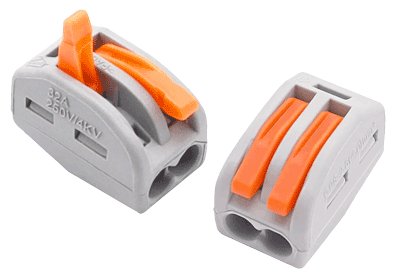
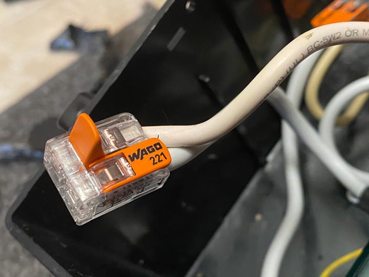
- Lever Lock Wire Connectors and/or Butt Connectors (12-10 AWG)
- Screwdrivers (Standard & Phillips)
- Wire Cutters & Strippers
- Masking Tape & Marker
- Voltmeter or Digital Multimeter (For Troubleshooting & Testing)
Ours is a 30 Amp switch! If your rig has 50 Amp power, be sure to get a 50A Transfer Switch.
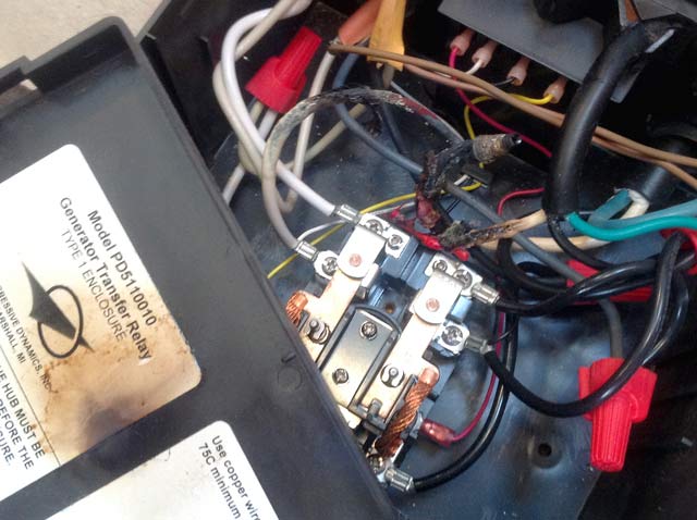
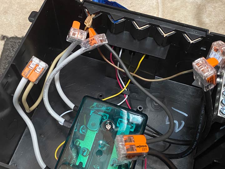
Do not use wire nuts! (See first photo above.) Lever Lock Wire Connectors provide a more secure connection and prevent loosening of wiring connections from motion of vehicle.
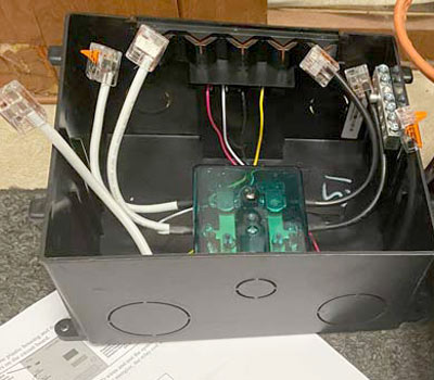
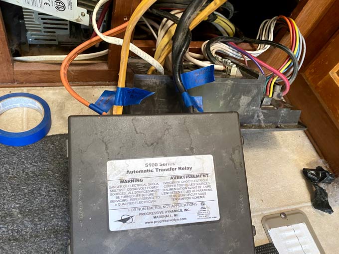
NOTE: There are various models of ATS relay boxes available which should meet the needs for your repair transfer switch project. I was impressed with the PDI 5100 Transfer Relay Switch because the pigtails include secure lever lock connectors and the contacts are protected under a clear cover.
Depending upon how easy it is to access your transfer switch ? and how tidy the wiring is ??getting ready for your repair project may be the hardest part. Our ATS is tucked behind the breaker panel in a tiny spot with a mess of wires.
1. Disconnect Power & Prepare Workspace to Repair Transfer Switch
Turn power off at the pedestal, or disconnect the cord. In addition, make sure your inverter is turned off. This will ensure that you have no hot wires coming into the transfer relay switch box. If your RV is like most rigs, you’ll likely be working in a tight uncomfortable space. Make sure you have all the parts and tools you’ll need to repair transfer switch within reach. Have a rag or vacuum handy for cleaning up any dust ? and furballs if you have furkids.
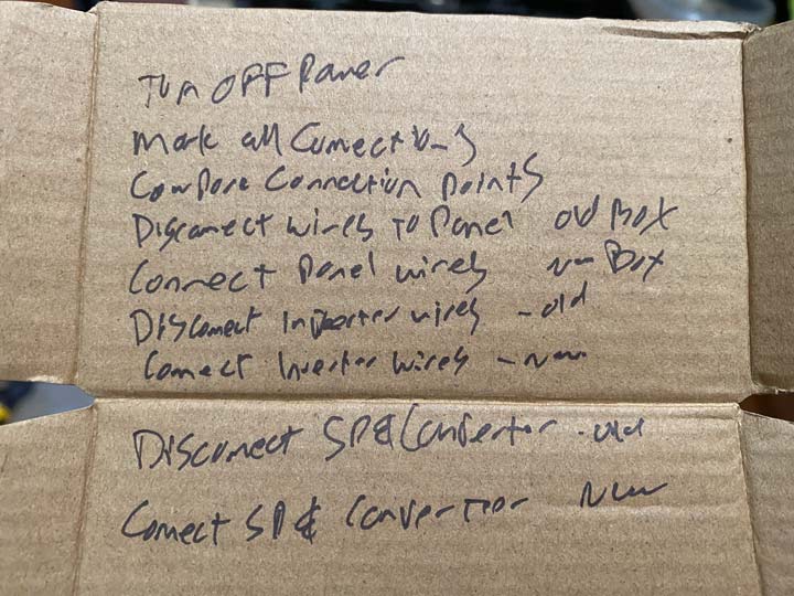
TIP: Grab your phone to take “before” pictures prior to disconnecting any wires. Therefore, you can have a reference when you forget which wires go where.
2. Mark All Current Connections
See what I did there? Current connections! Get it? Never mind. Use masking tape and a marker to identify all the existing wiring connections. Identify which wires are coming from where. Then confirm which other wires are going wherever. By marking the wires and noticing their connection points in the bad relay, your repair transfer switch project will go quick and easy.
3. Transfer Wiring to Repair Transfer Switch
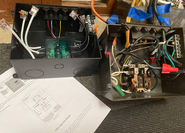
Disconnect and reconnect all wires to their corresponding posts in the new ATS relay box. To avoid incorrect wiring, work with one connection at a time. Remove each set of wires from the old box. Then, connect them to the corresponding connection points in the new box. Use the marked wires as your guide.
a. Connect breaker box wires.
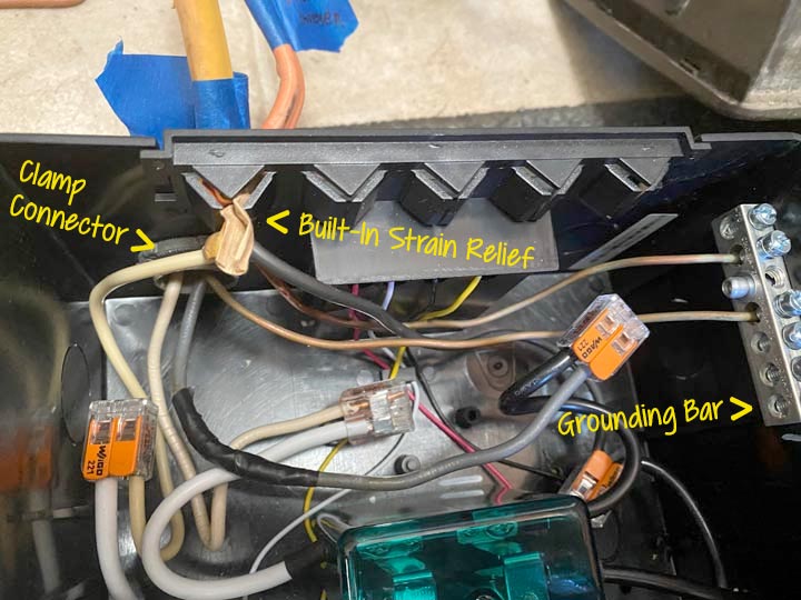
Disconnect the white, black, and ground wires of the breaker panel connection from the bad transfer switch. Connect each wire to the same locations in the new box. The ground wire will likely be a bare copper wire. Loosen one of the screws on the grounding bar and insert the wire. Then tighten the screw to secure the ground wire in place. Use the lever lock nuts on the ATS pigtail wires to connect the white and black wires to the AC Load (output) side of the automatic transfer switch.
Push the circuit wire (all 3 wires, shielded together) through the built-in strain reliefs. These gate-like openings in the ATS box prevent wires being pulled back out. As a result, the secure wiring connections will remain in place if tension is applied to the wires when the box moves.
b. Connect source wires from inverter.
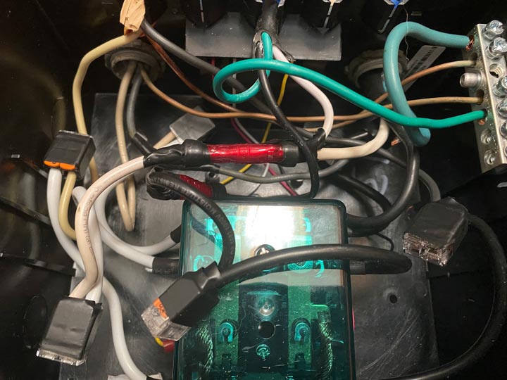
Disconnect the white, black, and ground wires of the circuit coming from the inverter to the bad transfer switch. The ground wire will likely be a green shielded wire. Strip enough shielding to expose bare wire you’ll connect to the corresponding points in the new box.
Connect the green wire to the grounding bar. Connect the white and black wires to the Generator pigtails of the automatic transfer switch. (Ours was originally wired to act as Shore Power as I described above. Therefore I kept the same configuration, as you may notice in the photos.)
For the larger wires, remove and reuse the screw-in strain reliefs for each circuit. Punch out a hole in the new ATS box. Insert the clamp connector and screw it together. Then, you can insert the wiring through the clamp and secure it with the two small crews. This provides strain relief for the wiring connections.
c. Connect source wires from shore power.
NOTE: Wires coming from both the RV power cord and converter must be connected to the shore power connection points.
Use Lever Lock or Butt Connectors to combine the leads for connecting to the post pigtails. White wires will connect to the white pigtail, black to black, and green to separate ports on the grounding bar.
For added security, tape down the lever locks and seal any butt connectors with electrical tape. Secure the clamp connectors and tug on the strain relief gates to ensure no movement of any wires inside the box. Tuck all wires down and secure the lid of the ATS box. As a result, you’re now ready to test your transfer switch repair.
4. Test Your Work and Clean Up
Before tucking everything back in place, check your work. First, turn on your inverter. If you wired your repaired transfer switch like I’ve done, you should immediately have AC power at all outlets. (See my explanation above regarding default wiring.) Turn off your inverter. As a result, AC power will be cut off from the distribution panel.
Turn power back on at the RV pedestal, or plug your shore power back in. Wait 20-45 seconds. You should soon have AC power again. There is one very easy sign to indicate you have AC power. The microwave will beep. At least ours does. And that is now music to my ears.
Any questions about how to repair transfer switch?
If you need to repair your automatic transfer switch, follow these simple steps to replace and rewire the ATS box. Installing a new RV solar power system, or rewiring your generator? You can take these same steps to install a transfer switch. As a result, you will be able to automatically switch from one source of power to the other. Any questions?
NOTE: Here’s another reason I love the Progressive Dynamics Transfer Switch. The quick change circuit board is easily replaced in the event of failure. Bad contacts may not be the problem of your bad transfer switch. The board may have failed. If this is the case, there is no need to disconnect and reinstall the entire unit as I’ve described.